VLAN Routing and Bridging on a Cisco Router Using the IRB
by Wenwei Weng
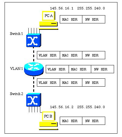
In order for a VLAN to span a router, the router must be capable of forwarding frames from one interface to another, while maintaining the VLAN header. If the router is configured for routing a Layer 3 (network layer) protocol, it will terminate the VLAN and MAC layers at the interface a frame arrives on. The MAC layer header can be maintained if the router is bridging the network layer protocol. However, regular bridging still terminates the VLAN header. Using the IRB feature in Cisco IOS® Release 11.2 or greater, a router can be configured for routing and bridging the same network layer protocol on the same interface. This allows the VLAN header to be maintained on a frame while it transits a router from one interface to another. IRB provides the ability to route between a bridged domain and a routed domain with Bridge Group Virtual Interface (BVI). The BVI is a virtual interface within the router that acts like a normal routed interface that does not support bridging, but represents the comparable bridge group to routed interfaces within the router. The interface number of the BVI is the number of the bridge group that the virtual interface represents. The number is the link between the BVI and the bridge group.

When you configure and enable routing on the BVI, packets that come in on a routed interface, which are destined for a host on a segment in a bridge group, are routed to the BVI. From the BVI, the packet is forwarded to the bridging engine, which forwards it through a bridged interface. This is forwarded based on the destination MAC address. Similarly, packets that come in on a bridged interface, but are destined for a host on a routed network, first go to the BVI. Next, the BVI forwards the packets to the routing engine before it sends them out of the routed interface. On a single physical interface, the IRB can be created with two VLAN sub-interfaces (802.1Q tagging); one VLAN sub-interface has an IP address that is used for routing, and the other VLAN sub-interface bridges between the sub-interface used for routing and the other physical interface on the router. Since the BVI represents a bridge group as a routed interface, it must be configured only with Layer 3 (L3) characteristics, such as network layer addresses. Similarly, the interfaces configured for bridging a protocol must not be configured with any L3 characteristics.
IRB configuration example
Network topology
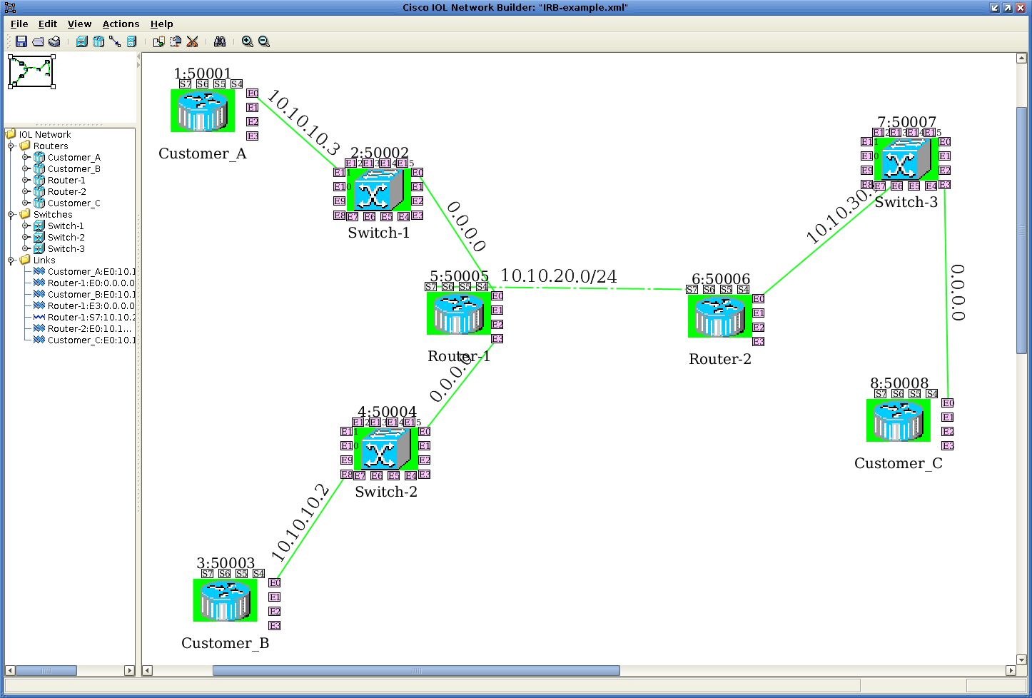
I’m running Cisco IOL to simulate Cisco Router and Switch. See tolopogy below:

The Router Customer_A,Customer_B,Customer_C act as end point device. A & B has the interface in the same subnet (10.10.10.0/24), but connect to Router_1 different L3 interfaces. Router_1 has BVI interface configured with IP address 10.10.10.1, and has members of interface E0/0 and E3/0. Router_1 has a serial WAN link to Router_2, the link has IP subnet of 10.10.20.0/24. There is another interface E0/0 in Router_2, which has IP address 10.10.30.1, and in the same subnet as Customer_C, which has E0/0 with IP address 10.10.30.2.
With above setup, when Customer_A pings 10.10.10.2 in Customer_B, Router_1 will simply bridge the packet from E0/0 to E3/0 in Router_1, which will be eventually devlier to E0/0 in Customner_B, because they are in the same subnet. When Customer_A pings 10.10.30.2 in Customer_C, the packet will be routed to Router_2, the packet will be switched to Customer_C E0/0 interface.
Following the running configuration of each router:
Configuration example
Customer_A
Customer_A#show running-config
Building configuration...

Current configuration : 3072 bytes
!
version 15.1
service timestamps debug datetime msec
service timestamps log datetime msec
no service password-encryption
!
hostname Customer_A
!
boot-start-marker
boot-end-marker
!
!
!
no aaa new-model
clock timezone PST -8
!
!
ip cef
no ipv6 cef
!
interface Ethernet0/0
 ip address 10.10.10.3 255.255.255.0
!
interface Ethernet0/1
 description !DO NOT USE!
 no ip address
 shutdown
!
............................................................
!
interface Serial7/3
 description !DO NOT USE!
 no ip address
 shutdown
 serial restart-delay 0
!
ip forward-protocol nd
!
!
no ip http server
ip route 0.0.0.0 0.0.0.0 10.10.10.1
!
!
!
!
control-plane
!
!
line con 0
 logging synchronous
 transport output all
line aux 0
line vty 0 4
 login
 transport input all
!
!
end

Customer_A#
Customer_B
Customer_B#show running-config
Building configuration...

Current configuration : 3072 bytes
!
version 15.1
service timestamps debug datetime msec
service timestamps log datetime msec
no service password-encryption
!
hostname Customer_B
!
boot-start-marker
boot-end-marker
!
!
!
no aaa new-model
clock timezone PST -8
!
!
ip cef
no ipv6 cef
!
!
interface Ethernet0/0
 ip address 10.10.10.2 255.255.255.0
!
interface Ethernet0/1
 description !DO NOT USE!
 no ip address
 shutdown
!
......
interface Serial7/3
 description !DO NOT USE!
 no ip address
 shutdown
 serial restart-delay 0
!
ip forward-protocol nd
!
!
no ip http server
ip route 0.0.0.0 0.0.0.0 10.10.10.1
!
!
!
!
control-plane
!
!
line con 0
 logging synchronous
 transport output all
line aux 0
line vty 0 4
 login
 transport input all
!
!
end

Customer_B#
Router_1
Router-1#show running-config
Building configuration...

Current configuration : 3187 bytes
!
version 15.1
service timestamps debug datetime msec
service timestamps log datetime msec
no service password-encryption
!
hostname Router-1
!
boot-start-marker
boot-end-marker
!
!
!
no aaa new-model
clock timezone PST -8
!
!
ip cef
no ipv6 cef
!
!
bridge irb
!
!
interface Ethernet0/0
 no ip address
 bridge-group 1
!
interface Ethernet0/1
 description !DO NOT USE!
 no ip address
 shutdown
!
interface Ethernet0/2
 description !DO NOT USE!
 no ip address
 shutdown
!
interface Ethernet0/3
 description !DO NOT USE!
 no ip address
 shutdown
!
interface Ethernet1/0
 no ip address
 shutdown
!
.........................................................
!
interface Serial7/0
 ip address 10.10.20.1 255.255.255.0
 serial restart-delay 0
!
interface Serial7/1
 description !DO NOT USE!
 no ip address
 shutdown
 serial restart-delay 0
!
interface Serial7/2
 description !DO NOT USE!
 no ip address
 shutdown
 serial restart-delay 0
!
interface Serial7/3
 description !DO NOT USE!
 no ip address
 shutdown
 serial restart-delay 0
!
interface BVI1
 ip address 10.10.10.1 255.255.255.0
!
ip forward-protocol nd
!
!
no ip http server
ip route 10.10.30.0 255.255.255.0 10.10.20.2
!
!
!
bridge 1 protocol ieee
bridge 1 route ip
!
control-plane
!
!
line con 0
 logging synchronous
 transport output all
line aux 0
line vty 0 4
 login
 transport input all
!
!
end

Router-1#
Router_2
Router-2#show running-config
Building configuration...

Current configuration : 3081 bytes
!
version 15.1
service timestamps debug datetime msec
service timestamps log datetime msec
no service password-encryption
!
hostname Router-2
!
boot-start-marker
boot-end-marker
!
!
!
no aaa new-model
clock timezone PST -8
!
!
ip cef
no ipv6 cef
!
!
interface Ethernet0/0
 ip address 10.10.30.1 255.255.255.0
!
interface Ethernet0/1
 description !DO NOT USE!
 no ip address
 shutdown
!
.........................................................
!
interface Serial7/0
 ip address 10.10.20.2 255.255.255.0
 serial restart-delay 0
!
interface Serial7/1
 description !DO NOT USE!
 no ip address
 shutdown
 serial restart-delay 0
!
interface Serial7/2
 description !DO NOT USE!
 no ip address
 shutdown
 serial restart-delay 0
!
interface Serial7/3
 description !DO NOT USE!
 no ip address
 shutdown
 serial restart-delay 0
!
ip forward-protocol nd
!
!
no ip http server
ip route 10.10.10.0 255.255.255.0 10.10.20.1
!
control-plane
!
!
line con 0
 logging synchronous
 transport output all
line aux 0
line vty 0 4
 login
 transport input all
!
!
end

Router-2#
Customer_C
Customer_C#show running-config
Building configuration...

Current configuration : 3072 bytes
!
version 15.1
service timestamps debug datetime msec
service timestamps log datetime msec
no service password-encryption
!
hostname Customer_C
!
boot-start-marker
boot-end-marker
!
!
!
no aaa new-model
clock timezone PST -8
!
!
ip cef
no ipv6 cef
!
!
interface Ethernet0/0
 ip address 10.10.30.2 255.255.255.0
!
interface Ethernet0/1
 description !DO NOT USE!
 no ip address
 shutdown
!
...........................................................
!
ip forward-protocol nd
!
!
no ip http server
ip route 0.0.0.0 0.0.0.0 10.10.30.1
!
control-plane
!
!
line con 0
 logging synchronous
 transport output all
line aux 0
line vty 0 4
 login
 transport input all
!
!
end

Customer_C#
Ping test
Customer_A#
Customer_A#ping 10.10.10.2
Type escape sequence to abort.
Sending 5, 100-byte ICMP Echos to 10.10.10.2, timeout is 2 seconds:
.!!!!
Success rate is 80 percent (4/5), round-trip min/avg/max = 1/1/4 ms
Customer_A#ping 10.10.30.2
Type escape sequence to abort.
Sending 5, 100-byte ICMP Echos to 10.10.30.2, timeout is 2 seconds:
.!!!!
Success rate is 80 percent (4/5), round-trip min/avg/max = 12/18/24 ms
Customer_A#
Reference:
http://www.cisco.com/c/en/us/support/docs/lan-switching/integrated-routing-bridging-irb/17054-741-10.html
Subscribe via RSS